We’ve listed Frequently asked questions (FAQ) and answers pertaining to the theory and usage of Reed Switches, Reed Sensors and Magnets. Some of the answers also showcase videos from our YouTube channel, for a better understanding. In the following list of questions and answers, the terms Reed Switch, Reed Sensor, or Magnet Sensor can be used interchangeably.

The basic reed switch consists of two flattened ferro-magnetic reed blades, hermetically sealed in a dry inert-gas atmosphere within a glass capsule, thereby protecting the contact from contamination. The reeds are sealed in the capsule in cantilever form so that their free ends overlap and are separated by a small air gap. The reed blades of reed switches can be design to overlap at the center of the glass tube or off-set from the center of the glass tube, to offer better single blade flexibility.
A reed sensor is a device built using a reed switch that incorporates additional functionality, for example, the ability to withstand higher shock or vibration, molded packages with in-built magnets for form B or E type operation, easier mounting for automatic pick and place before SMD reflow, additional intelligent circuitry, etc.
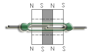
When a magnetic force is generated parallel to the reed switch, the reeds become flux carriers in the magnetic circuit. The overlapping ends of the reeds become opposite magnetic poles, which attract each other. If the magnetic force between the poles is strong enough to overcome the mechanical restoring force of the reeds, the reeds will be drawn together and the reed switch actuates.
Minimum force, expressed in Ampere Turns, will cause the reed based product to just close but the contact resistance at this stage will be high. Since the force between the poles increases as the gap decreases, a force of approximately half or 50% more than the just-operate force will maintain the operated state and ensure a low stable contact resistance. Speed of operation of the reed switch is determined by the excess of operating force over the just-operate force.
They are hermetically sealed in glass environment, free from contamination, and are safe to use in harsh industrial and explosive environments. Reed Switches are immune to electrostatic discharge (ESD) and do not require any external ESD protection circuits. The isolation resistance between the contacts is as high as 1015 ohms, and Contact Resistance is as low as 50 milli-ohms. Reed Switches can directly switch loads as low as a few micro-watts without needing external amplification circuits, to as high as 120W. When used in combination with magnets and coils, they can be used to form many different types of relays.
RRE’s reed switches are manufactured with flattened leads. This makes it easier for orienting and mounting for maximum in-group sensitivity, and no extra force (which could damage the seals) is required while SMD forming because the leads are already flattened. Ruthenium Sputtering provides low, stable Contact Resistance, long life, and prevents cold welding.
The basic reed switch is a normally open, Form A type contact. Form A types of contacts are available having different differentials ranging from 40% to 75%. A normally closed, Form B type contact is offered by biasing the Form A with a permanent magnet, and another magnet of opposite polarity needs to be used to actuate it. A latching or bistable type contact is offered biasing a Form A type of magnet with a weak magnet.
Single capsule Form C reed switches are available in many configurations depending on the manufacturer. All configurations fall into two main categories, those which use a magnet bias to hold the armature against one pole, and those which have the armature mechanically pre-loaded against one pole. The former is polarity sensitive, while the latter has a higher Contact Resistance on the closed contact.
A normally closed, Form B type of reed sensor is polarity sensitive and is actuated with the opposite polarity magnet. The video above indicates the change of stated from closed (buzzer on) to open (buzzer off) as a magnet of opposite polarity approaches the reed sensor.
A Form E type of reed contact is a latching or bi-stable type of contact. On magnet actuation, it stays in the last energized state, without the need for maintaining the magnet near the sensor. The state is altered by using the opposite pole of the magnet. The video above indicates the change of state from latched (buzzer on) to un-latched (buzzer off) and vice-versa.
A special Ferrite compound which loses its magnetic permeability at its Curie Temperature, is sandwiched between two permanent magnets. At temperatures lower than the Curie Point, the magnetic flux lines between the two exterior magnets are connected and enlarged as a whole. This keeps the reed switch contact closed. When the ambient temperature reaches the Ferrite’s Curie Temperature, the flux lines between the exterior magnets disconnect, and the reed switch contact opens. Normally open type of thermal reed sensors are made by positioning the magnet assembly, slightly away from the reed switch contact overlap.
| Reed Switches | Hall-effect Devices |
|---|---|
| Are hermetically sealed | Are susceptible to changes in the environment |
| Can be operated from -50°C to 150°C | Can be operated from 0°C to 70°C only |
| Immune to electrostatic discharge (ESD) | Requires ESD protection |
| Insulation resistance >1012 minimum | Insulation resistance >106 minimum |
| Typical breakdown voltage >250V | Typical breakdown voltage <10V |
| Contact Resistance ~50mΩ | Contact Resistance >200Ω |
| Does not require power for operation | Requires external power source for operation |
| No components needed to generate output | Requires many other components to generate output |
| Configurable hysteresis | Fixed hysteresis |
| Signal does not require any amplification | Requires amplification circuits |
| Switches a range of loads directly | Require external devices for switching loads |
| Does not drain battery in mobile devices | Constant drain of battery in mobile devices |
When storing Reed Switches, Reed Sensors, Magnets, and related products, care should be taken to ensure that the storage area is thermally stable, with not too fast a temperature change. The room should be maintained at less than 75% Relative Humidity. Another point to note is to avoid storing these products near strong magnetic fields such as large coils or transformers as this could increase the magnetic remanence of the reed blades. Strong magnetic fields could also make the reed switches operate or buzz, thereby reducing long term life.
The normal operating temperature range for a reed contact is -40°C to +200°C, but a steep rise or drop in temperature may crack the glass to metal seals. As the temperature rises, the Reed Blades lose some of their ability to carry magnetic flux and Reed Switches become less sensitive. Conversely, as the temperature drops, the reed switches become capable of carrying more magnetic flux and become more sensitive.
Ultrasonic cleaning or welding should be avoided as products could get damaged by ultrasonic frequencies. The excessive shock due to frequencies ranging from the resonance frequency and upwards, could alter the accurate gap between the contacts and also possibly damage the glass to metal seals. If ultrasonic welding is the only option, magnified visual inspection and electrical parameters tests will need to be conducted to ensure that the reed based products have not been damaged in any way.
As shown in the video, when the same magnet approaches two reed switches of different Operate AT, the one with the lower Operate AT, being more sensitive to magnetic fields, will close first. When an application requires a reed switch to only operate within a specific distance, and is flexible in terms of release distance, one need not be concerned with the Release AT of the reed switch.
As shown in the video, when the same magnet is moved away from two closed reed switches with identical Operate AT but different release AT, the one with the higher release AT, being less sensitive to magnetic fields, will open first. When an application requires a reed switch to operate and release within a specific distance range, reed switches should be selected specifying an Operate and a Release AT band.
| Pros | Cons |
|---|---|
| Very sensitive to magnetic fields | Lower resistance to shock and vibration |
| Can be used with inexpensive magnets | Very low contact gap acts like a capacitor |
| Magnet can actuate from farther away | Lower breakdown voltage |
| Lower operate time | Higher Contact Resistance |
The video above shows how the actuation of a reed switch is altered when its leads are cropped. The Operate AT and to a lesser extent, the Release AT, increase, but since the contact gap is not altered, the Breakdown Voltage is not changed. Severe shock during cropping or forming, caused by hand tools, will permanently alter the contact gap and all other parameters.
When using a reed switch in a circuit, the Switching voltage and switching current should not exceed their individual maximum ratings given in the specification. Care should also be taken that the product of voltage and current in the sensing circuit should not exceed the maximum contact rating, in watts, stated in the specifications.
| Center Contact | Off-center Contact |
|---|---|
| More resistant to shock and vibration | Less resistant to shock and vibration |
| Wide Differential | Close Differential |
| Used when magnet approaches sideways | Used when magnet approaches from the seal or lead end |
| Longer glass length | Shorter glass length |
Ferro-magnetic parts such as screws, nuts, bolts increase or decrease the magnetic flux that an actuating magnet brings towards a reed switch. Other sources of magnetic interference may also be caused by nearby motors, coils and relays. Such parts can cause early or late operation, intermittent operation, or no operation at all.
All measurements should be taken only using test sockets with 4 terminal Kelvin Sensing method, to clamp the device under test. The first step is to apply a saturation pulse to the test coil, then increase the coil drive gradually up to the point the reed contact closes. This is the operate AT of the reed switch. Contact resistance across the reed switch leads should be measured after giving a 25% over-drive to the test coil, beyond the voltage at which the reed switch operated. The coil ramp should now be decreased gradually to the point the reed switch opens. This is the release AT of the reed switch. More information on testing can be found here.
When measuring the Ampere-turn of a reed switch using a test coil, one should ensure that the coil is vertical. If the test coil can only be placed horizontally, it is recommended to that it should be oriented in an East-West direction, being perpendicular to the Earth’s magnetic field. The reed switch glass seal should be perfectly centered to the test coil. There should not be any external magnetic fields or Ferrous parts in the vicinity. The testing room temperature should be controlled between 25°C and 30°C.
In general, there will be little benefit derived from using a coil whose dimensions are significantly greater than those of the appropriate test coil for a reed contact. If the object is to operate the reed switch with the minimum coil dissipation, the inner diameter of the winding should be made as small as possible and the winding length should be approximately two-thirds the overall length of the switch. Sensitivity can be further increased and, therefore, coil dissipation further reduced, by wrapping a low-coercivity Ferro-magnetic foil around the outer diameter of the coil. The foil also constitutes a shield which reduces inter-action between the reed relay and its environment.
When using reed switches with a coil and when the actuating coil current is stopped, the release time is invariably less than 0.5 ms. If the coil transient is suppressed with a resistor capacitor network, the release time will be shortened. But if the coil current is sustained by a suppression diode in parallel with the coil, the reed switch release time will be increased by two to three times.
Bounce time can be reduced by using stronger magnets, by making sure the magnet moves closer to the reed switch during actuation, or by giving a higher voltage to the Coil. The leads of a Reed Switch should not be cropped too short as reed switches with shorter leads tend to bounce more.
