Protection Circuits for Reed Switches
It is assumed that the ideal reed switch load is a Resistive Load, but it is almost impossible to reduce any load to purely resistive. Therefore, when a Reed Switch is to be connected to an Inductive load or a load where Inrush Current flows (such as a Capacitive Load or a Lamp Load), contact protection circuits are required, in order to increase the life of the reed switch.
Inductive Loads
Inductive Loads can be damaging to Reed Switches on opening due to the high load of induced back EMF. In other words, when a reed switch is used with an electromagnetic relay or solenoid, the energy stored will cause an inverse voltage when the reed contacts break. The voltage, although dependent on the inductance value, sometimes reaches as high as several hundred volts and becomes a major factor to deteriorate the contacts. The following circuits provide inductive load suppression for the reed switch. The more effective the suppression circuit, the longer is the release time of the suppression load.
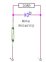 | The simplest method of suppressing DC inductive circuits is with a diode wired across the load. With the diode in the circuit, the Back EMF is directed through the diode instead of the reed switch. The diode should be selected with a forward current rating that is at least as high as the steady current of the circuit in question. |
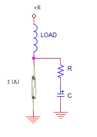 | The most commonly recommended protection for AC Inductive Loads is the Resistor-Capacitor (RC) network. The values for the resistor and the capacitor in the RC network protection (connection to load terminal also allowed) are: |
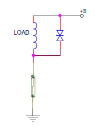 | Contact Suppression can also be achieved in the circuit with varistor (connection to contact lead also allowed). If the open state of the contact continues for a relatively long time, the protection circuit should be connected to the same terminal. |
Lamp Load
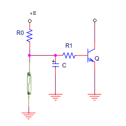
When a reed switch is to be used to switch a tungsten filament lamp, the resistance of the cold filament is around 1/10th before it is switched on and increases after switching on, followed by lighting with a steady-state current. The Inrush Current (5 to 10 times the steady state current) will flow in the contacts immediately after the lamp is turned on, causing melting or sticking of the contacts. The reed switch contact can be protected with a series resistor calculated to reduce the surge. Alternatively, the filament can be kept warm by means of a bias current, again avoiding the high Inrush current.
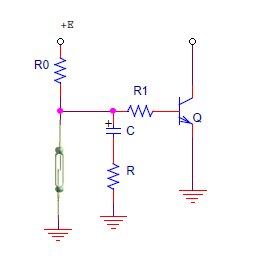
 | R should be decided so that Is < 0.5A can be obtained R = current limiting resistor |
 | R = Parallel Resistance By connecting R, the filament is heated and its resistance is made higher and |
Capacitive Loads
Capacitive Loads as low as 50 pF, which could even be caused by the wiring between the reed switch and the load, could enough to reduce the life. In case a capacitor is connected in series or in parallel with a reed switch in a closed circuit, the Inrush Current which flows during charge and discharge of the capacitor, will cause deterioration of the reed contacts. The simplest Suppression Circuit is to place a resistor in series with the reed switch and as close to the reed switch to limit the surge current. Shown below are typical examples of protection circuits to prevent the rush current.
 | Circuit without contact protection. The energy stored in capacitor C will cause the rush current (Is) when the contact closes. |
 | Circuit with capacitor C for chattering protection. The rush current will also be caused as in circuit A. |
 | Circuit with resistor R for contact protection, R=50-500 ohms. |
Wiring Capacitance
In case a reed switch is connected to a load by cable, over a long distance, static capacitance caused by the cable will affect the contact characteristic of the reed switch. Although it depends on the type of cable used, it is recommended that if the cable length exceeds 50 meters, protection as per the circuit below is required for longer operating life of the reed switch.
 | The surge suppressor (Ls) inserted near the reed switch contacts makes the rush current flowing to the contacts to be delayed. The value of Ls can be replaced by a very small resistance (current-limiting resistor) of 10 to 500 ohms. |